
Skyline-R33
RMS Regular
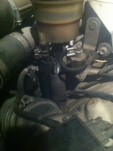
hi guys basicaly have a problem being trying to put a Hks Boost controller in my skyline but the Hks Solenoid has 3 out going connections but i dont have 3 pipes could someone show me what the standard boost solenoid should look like as i had a manual boost controler in sold it and ripped it out and just joined the pipes with a t-piece and car isint running the best. Compared it to a friends spec 2 who doesnt have a front mount and has a pipe from the boost solonoid to his hard pipe. I have a front mount intercooler filled also so dont have the connection onto the hard pipe.
so im basicaly wanting to see pics of someones to know exactly what pipe goes where
so im basicaly wanting to see pics of someones to know exactly what pipe goes where


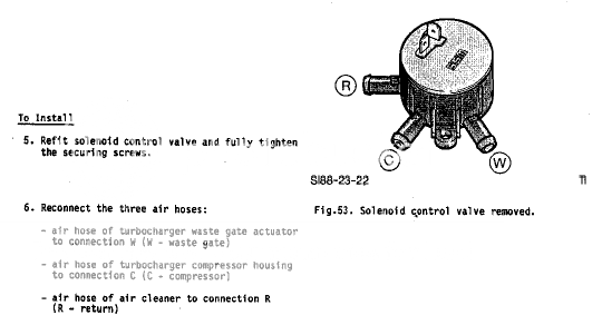
 His is showing that basically you have the compressor housing connected directly to the actuator = no boost control at all apart from the actuator spring.