

You are using an out of date browser. It may not display this or other websites correctly.
You should upgrade or use an alternative browser.
You should upgrade or use an alternative browser.
The Ultimate X - Fiat X1/9
- Thread starter Mark Bowden
- Start date
pablo
RMS Moderator
- Messages
- 67,032
- Location
- Glengrimley
I’m sure you have your reasons but such a shame to lose the pop ups
IL
RMS Regular
- Messages
- 10,278
- Drives
- 981 GTS
I’m sure you have your reasons but such a shame to lose the pop ups
Agreed - pop ups are cool! What is the reason? Better lighting? unreliable system? weight?
pablo
RMS Moderator
- Messages
- 67,032
- Location
- Glengrimley
Mark Bowden
RMS Regular
OP
- Messages
- 218
- Thread Starter
- #282
I really wasn't happy with the first version so I had to make a second version mounting the lamps completely inside the body.
Here is the nearside pair first successful dry assembly -


I will have to make a clear acrylic outer lens that is flush with the aperture, on the front part and a top which will be aluminium...
 I now have to copy this version to the other side...
 l will then break everything down for painting before final assembly and post detail shots idc.
Here is the nearside pair first successful dry assembly -
I will have to make a clear acrylic outer lens that is flush with the aperture, on the front part and a top which will be aluminium...
svensktoppen
RMS Regular
- Messages
- 32,823
- Drives
- FK2 CTR
That's better, will look cleaner I think. For what that's worth 
Mark Bowden
RMS Regular
OP
- Messages
- 218
- Thread Starter
- #284
I decided to delete the pop ups for various reasons -
Save weight
Reduce complexity
Increase brightness
Reduce drag
A problem with pop ups is the nacelle is open to the outside, I guess some designs have a rudimentary seal but on the X1/9 there's also a water gutter across the top of the nose cone and along the tops of the wings.
The gutter drains into the lower front corners, pours down over the wiring loom and horns, and out through a hole in the valence.
I plan to fill the gutter completely the bonnet panel gap shadow line will be a black flush seal in other words.
Mark Bowden
RMS Regular
OP
- Messages
- 218
- Thread Starter
- #285
Mark Bowden
RMS Regular
OP
- Messages
- 218
- Thread Starter
- #286
Installed the projectors successfully within the reduced space, and I'm puzzling out the design of the outer lens.
Originally I imagined a single piece of moulded acrylic and so first I made a blank out of 1mm aluminium thinking it would be used as the top side of the mould...
 but when I fitted it to the car it looked so neat I thought it would be nice to have a pair of these at least to protect the lamps during daytime running or just for show.
So I made a duplicate using a transparent template, which shows how two circles form compound curves off the side elevation above and below the plimsoll line...
 ... from which I could just about derive the shape of the cutouts by eye but its very difficult to mark the line accuracy , the end result is not exactly right but it does illustrate the idea...
 same angle zoomed out:
 more oblique angle:
 this gives a good impression of how the front will look like when the car's finished, I think, despite the fact this view is from the perspective of a cat or small dog and unless you were lying in the street you would never see it like this.
I have tested the lamps and the peripheral occlusion of the beams caused by the "frame" is negligible .
.
Therefore I plan to try and bond a sheet of 1mm clear acrylic to the outside face, covering the entire piece, which will cancel the step change caused by the top edge going under the back section of the cover, which returns through 2 angles finishing the corner section of the water gutter running in the top of the wing and across the nose cone, in the bottom left hand corner of this pic:
 In terms of finishes, I will have all the pieces anodised first, externally the back and front pieces logically should be the body colour apart from the rolled edge and lip detail along the bottom edge that divides the headlamp section from the indicator sidelight section, which is interested because it could be the body colour and make the division obvious, or it could be black as per the rest of the factory dechromed parts, or polished and clear lacquered... details details.
The aluminium lens frame, could be polished and left unfinished if I use Stix-All glazing silicone and trap no bubbles but more likely I will just mask off the ovals and spray the rest red.
Anyway, I'm going to make 2 pairs of interchangeable pieces, one with cutouts for the lamps and one without.
FTW
Originally I imagined a single piece of moulded acrylic and so first I made a blank out of 1mm aluminium thinking it would be used as the top side of the mould...
So I made a duplicate using a transparent template, which shows how two circles form compound curves off the side elevation above and below the plimsoll line...
I have tested the lamps and the peripheral occlusion of the beams caused by the "frame" is negligible
.Therefore I plan to try and bond a sheet of 1mm clear acrylic to the outside face, covering the entire piece, which will cancel the step change caused by the top edge going under the back section of the cover, which returns through 2 angles finishing the corner section of the water gutter running in the top of the wing and across the nose cone, in the bottom left hand corner of this pic:
The aluminium lens frame, could be polished and left unfinished if I use Stix-All glazing silicone and trap no bubbles but more likely I will just mask off the ovals and spray the rest red.
Anyway, I'm going to make 2 pairs of interchangeable pieces, one with cutouts for the lamps and one without.
FTW
svensktoppen
RMS Regular
- Messages
- 32,823
- Drives
- FK2 CTR
That's a lot of work, coming together nicely. All in the detail like you say. I wouldn't even know where to start doing something like that from scratch.
Mark Bowden
RMS Regular
OP
- Messages
- 218
- Thread Starter
- #288
Thank you Sven.
I think it boils down to patience plus the desire to realise a concept.
This is: a pair of lamps and a car body shell neither of which can be modified beyond a certain point.
I did literally saw through the lamps and saw through the bodywork to get them to fit and I probably took off a bit more than I needed to haha but not too much know what I mean
I built the first prototype based on adjusting the beams from the front only, before I worked out the adjusters could be reversed they are designed to be adjusted from the front or the back, on the dip beam but on the spot beam I had to cut one end off the bolt, works fine.
The second prototype had ports in the rear plate just in case I could get on to the adjusters from the back, ie through the headlamp access panel in the top of the inner front wing.
Very luckily I was able to get on to all the adjusters this way, just as well because with all the necessary plates, rails, brackets etc that form the top and sides and floor of the unit (fully built up except for the outer lens), meant that I could not install or uninstall the lamps in the planned, correct sequence from the top with the lid off.
That's what happens when things go badly wrong and I nearly gave up on the whole idea right away.
Slept on it, woke up thinking it might be possible to change the assembly sequence so that the adjuster plates are installed on the base plate without the lamps, first, then the lamps are fitted from the front by screwing them on from the back, through the ports.
So then I had to do a complete disassembly and reassembly, and to my surprise it actually worked.
That's really a short version of the last four months of fiddling about, haha
svensktoppen
RMS Regular
- Messages
- 32,823
- Drives
- FK2 CTR
Easy is boring, lol
Mark Bowden
RMS Regular
OP
- Messages
- 218
- Thread Starter
- #291
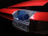
Internal view looking down through the headlamp access panel, showing the back wall of the box, parts of the adjuster rings, and the base plate.
The box is "L" shaped, hangs from the access panel frame at the top and is fixed down to the ledge above the indicator sidelight, at the front.

At the top, there is a tension/compression rail for the adjustable tie rods that lock the tops of the rings in position but allow for some coarse up down adjustment of the beam angles
 The tie rods go through the rings like this

The box is "L" shaped, hangs from the access panel frame at the top and is fixed down to the ledge above the indicator sidelight, at the front.
At the top, there is a tension/compression rail for the adjustable tie rods that lock the tops of the rings in position but allow for some coarse up down adjustment of the beam angles
Mark Bowden
RMS Regular
OP
- Messages
- 218
- Thread Starter
- #292
Overall view of the complete nacelle without lens, lamps, or top cover...

 ... looks like this with top cover and blank lens fitted -
 ... the blank section on its own is just this -

Seems I have missed this project thread up until now. But will be following from now on.
Looks like an interesting project and you seem to be doing a great job. Didn't have as much of a read through it as I would have liked because I don't have the time but what I did see looked great.
Looks like an interesting project and you seem to be doing a great job. Didn't have as much of a read through it as I would have liked because I don't have the time but what I did see looked great.
Mark Bowden
RMS Regular
OP
- Messages
- 218
- Thread Starter
- #294
Mock ups f
Thank you, the car should be finished in a year or two, still to do is the floor area under the frunk, front wheel arches, front suspension, windscreen, headlamps, number plate brackets... before filling the cooling and hydraulic systems and starting the engine for the first time.Seems I have missed this project thread up until now. But will be following from now on.
Looks like an interesting project and you seem to be doing a great job. Didn't have as much of a read through it as I would have liked because I don't have the time but what I did see looked great.
Mark Bowden
RMS Regular
OP
- Messages
- 218
- Thread Starter
- #295
Mock ups for the lens section and it's logical division into left/ right where there could be a clear acrylic or solid aluminium vertical divider for added strength...


Good things worth dong take time.Thank you, the car should be finished in a year or two, still to do is the floor area under the frunk, front wheel arches, front suspension, windscreen, headlamps, number plate brackets... before filling the cooling and hydraulic systems and starting the engine for the first time.
")
Mark Bowden
RMS Regular
OP
- Messages
- 218
- Thread Starter
- #297
This is the view looking towards the front right corner of the car, from the inside of the nacelle.
To repair the bodywork properly would mean cutting off the entire outer wing back to the A pillar, cutting out the headlamp access frame, cutting out the headlamp motor support bracket and welding in new panels.
In fact, when I bought the car it was in a mess in this area.
I noticed the right side headlight was wobbly like it was loose.
I assumed it was play in the hinges or mechanism or in the adjusters or in the bowl mounts, I went through the whole lot even replaced all the diodes.
Made no difference, still really wobbly.
Close inspection revealed, when switching on the lights the whole front part of the wing was visibly moving down as the pod went up!
Grabbing the pod and wrenching it around, revealed the whole area was only just holding together.
I fired a bolt thru the corner, used it with 4 nuts like an adjustable length tie rod, to pull /push it back together.
The front right corner of the access frame was bent down slightly, and the support bar bent up slightly, during this process.
This unfortunately meant that the top pair of adjusters were in line with the front of the access frame, meaning they could not be adjusted from above or below the frame.
It took a lot of trial and error to find a way through but I found a line just above the water gutter...
So in total there are 8 adjusters accessible through the back...
svensktoppen
RMS Regular
- Messages
- 32,823
- Drives
- FK2 CTR
That's a lot of engineering 
Mark Bowden
RMS Regular
OP
- Messages
- 218
- Thread Starter
- #299
First test of the daytime running lights...

It's difficult to gauge the brightness, this is taken at dusk and is totally, 4 x 10W one pair of white LEDs and one pair of "retro" effect which are more yellow, quite nice.
Mixing the two, seems to create a better overall balance I guess on account of increasing the spectrum, or bandwidth or whatever it's called
-
This site uses cookies to help personalise content, tailor your experience and to keep you logged in if you register.
By continuing to use this site, you are consenting to our use of cookies.